Manufacturing Test System – Aircraft turbine blade quality inspection
Improving quality by detecting blocked holes in aircraft turbine blades with an automated test system
Client – Large aerospace company
Challenge
Fuel-fed aircraft turbines run extremely hot. At very high temperatures, a turbine’s blades suffer a shorter life span than if run at cooler temperatures. Consequently, turbine manufacturers put cooling holes in the blades to lower the blade temperature during operation. These holes carry cool air or gas from the blade mount along channels that eventually arrive at holes in the blade surface. This practice keeps the blade much cooler than without the flow.
Some blades have a huge number of holes. Inspecting that each hole is open and has sufficient flow is time-consuming and, if inspected by a person, prone to error due to boredom and distraction. Plus, carpal tunnel syndrome issues are present due to repetitive motions. Multiply these issues by the large number of blades in each turbine and inspection becomes a significant effort.
Our client wanted to implement an automated inspection station to increase throughput and decrease mistakes. Sending defective blades down to the subsequent manufacturing steps is pure manufacturing waste when they are rejected at some later step. Reducing operator injury was also important.
Image courtesy of CC by 4.0 https://creativecommons.org/licenses/by/4.0/ from Zhang, R.; Liu, P.; Zhang, X.; Xi, W.; Liu, J.; “Recent Developments in the Aerodynamic Heat Transfer and Cooling Technology of Gas Turbines Endwalls”. Aerospace 2023, 10, 702. https://doi.org/10.3390/aerospace10080702
Solution
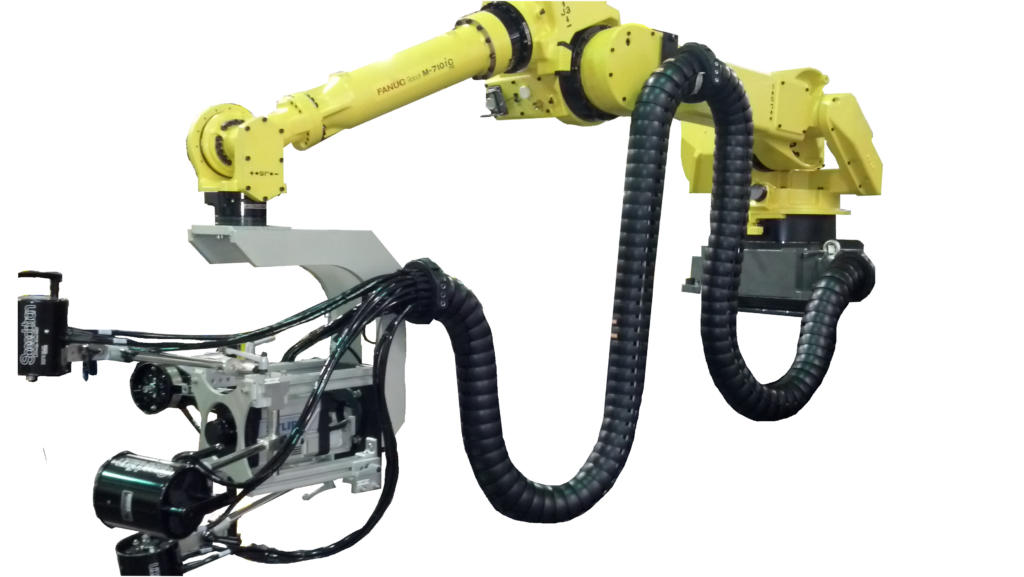
Collaborating with our client, we created a manufacturing inspection system that uses an IR camera and a robot to scan different regions on the blade under inspection. The camera is placed at specific locations and at various viewing orientations to fully inspect all the holes in the blade.
A PC running a LabVIEW test application manages the entire process. Safeties and control of access to the part under inspection are included to protect personnel and product. The system uses hardware sensors and switches and some via FPGA I/O to accomplish this safety monitoring.
Benefits
- The reliability, reproducibility, and speed of the automated inspection augments the operator capabilities
- Improved part quality of parts released to downstream production steps.
- The measurements collected during inspection of each part are available for quantitative analysis of the performance of the manufacturing processes. This post-inspection information helps improve quality all around.
Working Together
This project was the culmination of over 10 years of development effort between our client and Viewpoint engineers. We started a basic R&D proof of concept system.
After some tweaks to the process and associated system redesign, we were ready to use a prototype system in a trial run situation where manufactured parts were run manually. This stage gave confidence to those in manufacturing that the system would improve part inspection while speeding up the original manual inspection process. Some changes were made at this stage to decrease costs and improve the test engineer and operator interfaces. It was then placed into the production environment.
Along this entire multi-year development path, the level of automation was increased and the system design was adjusted as we learned from each other about what worked and what didn’t. For example, early in the R&D phase, attention was paid to the analysis algorithms and data required to make those reliable and accurate. And, for the production phase, we changed hardware components to make the system less expensive and more robust while reworking the user interface to be simpler to configure and run.
Both Viewpoint and our client formed a tight team during this journey, with one constant being the Viewpoint engineers involved as the various people on the client’s side changed as this inspection system moved through departments and physical location within our client’s facilities.
System Overview
The system is composed of the following items:
- LabVIEW test application running on a PC
- Robot and motion controller
- Vision system for IR camera
- NI Compact RIO FPGA digital I/O for controls and safeties
- NI Compact RIO analog I/O for equipment status
- Hardwired safeties and switches for operator and equipment protection
The LabVIEW application manages the entire inspection cycle:
- Assuring a part is present in the nest before starting the inspection process,
- Downloading the part-specific motion profile to the robot,
- Acquiring the images from the IR camera,
- Analyzing the images,
- Compiling the results, and
- Preparing a test report for the part.
Simultaneous with this cycle, the application checks digital and analog I/O for machine status and errors.
If a part model has not been inspected before, the LabVIEW application is used to create the motion profile for that part model.
When the test on a specific part is started, that motion profile is downloaded to the motion controller based on the part type as selected in the application.
After testing a part, the operator is presented with the test results where the option to accept, retest, or reject is offered. The operator is integral to this automated test. In any case, the test data is archived.
When the test is completed, the operator unloads the part for final disposition and loads the next part to inspect.
The LabVIEW application also has a diagnostic mode and configuration editor which is used by the operator or manufacturing engineer to evaluate and tune the inspection process.
The robot movement is managed by a motion controller based on the motion profile created via the LabVIEW application. The PC-based image acquisition is done when the motion controller alerts the LabVIEW application that the part is oriented and positioned within the field of view of the camera. Images are acquired for each of the positions defined in the motion profile.
Safety for both the operator and the part is handled in two ways. First, the Compact RIO FPGA checks system status via digital and analog inputs. Second, hardwired safety sensors and switches assure that the operator is out of the way when the robot starts moving and that the part is in the nest ready for inspection. An example of these “hard” sensors is a light curtain which will cause the system to stop if the curtain is affected during a test.
| SOFTWARE FUNCTIONS |
|---|
| NI FPGA for control and safeties |
| PC LabVIEW test application |
| System configuration |
| Data management |
| Safeties and machine status |
| HARDWARE USED |
|---|
| Articulated robot |
| Vision camera |
| FPGA digital I/O |
| FPGA analog I/O |
| Hardwired safety circuit for personnel and product protection |
| Touchscreen monitor |