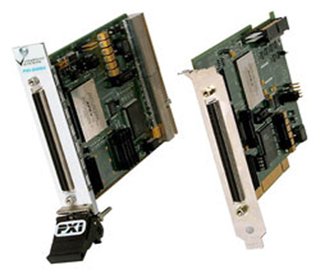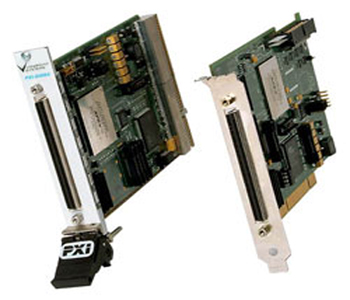
DIO-64 Event Analyzer/Control (No Longer Available)
Features
- Custom-coded Altera FPGA manages timestamped digital edges
- Time intervals as short as 50 nanoseconds.
- High channel count with 64 channels definable as input or output
- RTSI/PXI interface allows for multi-board triggers and clocks
- LabVIEW and DLL driver software with useful example programs included
Applications
- Long duration, high channel count digital data logger
- Demanding digital pattern stimulus outputs
- Digital encoder motion quality measurements
- Bose-Einstein condensate pulse and trigger control
The 64 TTL-level digital outputs can be configured for input or output in four 16-bit groups.
For input, the DIO-64 allows you to record and timestamp state changes on up to 64 digital inputs in LabVIEW®. Because the on-board FPGA program records only the changes, it eliminates redundant measurements when no changes have occurred. You can even specify the digital lines that can trigger a sample, leaving you with only the data of interest to you.
For output, by specifying only the bit pattern and the time of any changes, the DIO-64 simplifies description and creation of complex patterns on up to 64 digital output channels. The DIO-64 provides a large FIFO that can replay some desired patterns continuously or for a limited number of repetitions.
Using channels as both input and outputs gives you even more high performance flexibility.
The DIO-64 input mode monitors a specified number of digital input bits at a particular scan rate. This scan rate determines the minimum pulse duration that can be sampled. If any digital input changes from one scan to the next, the DIO-64 saves the current time and state of all the digital inputs into a FIFO. This FIFO is read by the application, where the sampled data can then be processed.
The DIO-64 output mode allows an application to describe a digital waveform that will be driven out the specified digital output bits. The application describes this waveform as a series of events. Each event describes the digital data to be generated at a specified timestamp. The DIO-64 will output an event out when the internal timer reaches the time specified by the event’s timestamp. The DIO-64 also allows the waveform to repeat for a fixed or continuous number of times.
The DIO-64 can perform both input and output simultaneously without sacrificing performance.
These specifications are typical for 25 ?C unless otherwise noted.
Digital I/O
Number of channels…………………………. 64 input/output (4 banks of 16 bits), 4 control pins
Compatibility…………………………………….. 5 V TTL/CMOS
Digital Logic Levels
| Level | Minimum | Maximum |
|
Input low voltage |
-0.5 V 5 ns |
0.8 V |
|
Output low voltage (Iout=24mA) |
– |
0.55 V |
|
Power-on state for outputs
PCI, PXI
Memory
|
Bus Interfaces
Clock Sources
|
RTSI Features (PCI Only)
PXI Features (PXI only)
Max Scan Rates
|
Power Requirements
|
+5 VDC (+/-10%) Device (Typical/Maximum)
|
Physical
Environment
|
Oven-Controlled Crystal Oscillator (OCXO)(optional)
|
Note: You can use the OCXO to replace the PXI 10 MHz backplane clock when the DIO-64 is installed in the PXI star trigger slot. (PXI only)
