Automated Manufacturing Test Systems for Medical Diagnostic Equipment
Using NI PXI and LabVIEW as a common architecture for multiple test systems testing several subassemblies
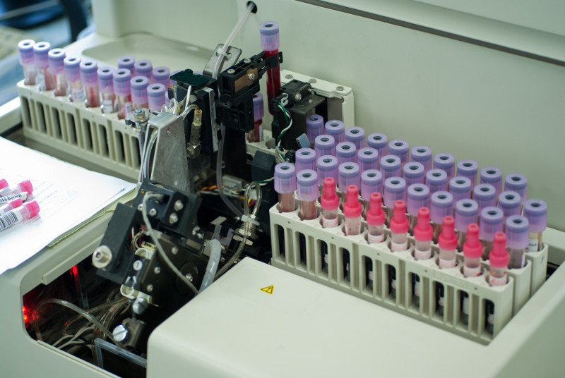
Client: a manufacturer of automated blood analysis machines
Challenge
Our client was embarking on a complete redesign of their flagship automated in-vitro Class 1 blood diagnostic machine. In order to meet schedule goals, the design and build of several automated test systems needed to occur in parallel with the overall machine. In a major design paradigm shift, many components of the machine were being manufactured as modular subassemblies, every one of which was an electro-mechanical device. Thus, multiple testers were required to test each of the specific subassemblies in the machine. And, since this was a medical device, the testers needed to comply to 21 CFR Part 820 and Part 11.

Solution
With a looming deadline, the testers needed a common architecture, so that all testers could leverage the development from the others. Since each subassembly could be tested independently of the overall machine prior to final assembly, the design of the testers was based on a common measurement and reporting architecture, written in LabVIEW, that interfaced to the customers Part 11 compliant database for testing procedures and measurement results. Furthermore, procedures and validation checks for calibration of the testers were part of the overall test architecture.
Benefits
- Modularization of the test system architecture aided development and maintenance
- Reduced overall development costs due to standardization of test sequence steps and reporting
- Both test sequences and test results were stored in a managed database that satisfied 21 CFR Part 11 requirements
- Modular and common software developed for the test systems reduced the V&V effort during IQ & OQ.
System Overview
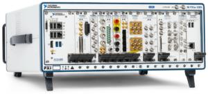
Since multiple subassemblies were being tested, with one part-specific test system per part, the automated test systems used as much common hardware as possible to simplify the development effort through common hardware drivers and test steps. Measurements were made with PXI equipment. Test steps and the test executive that executed the test sequence(s) were developed using LabVIEW.
The types of test steps required to verify the proper operation of each subassembly were categorized into basic operations, such as voltage reading, pulse counting, temperature reading, and communications with on-board microcontrollers. The specifics of each measurement could be configured for each of these measurement types so that each test step accommodated the needs of the specifics of each subassembly. For example, one subassembly might have needed to run the pulse counting for 2 seconds to accumulate enough pulses for accurate RPM calculation while another subassembly might have only needed 0.5 seconds to accomplish that calculation.
The configuration of a test step algorithm was accomplished via an XML description. The accumulation of these XML descriptions of each test step defined the test sequence run on that specific subassembly.
Test results were associated with these test sequences by completing the entries initially left blank in the test sequence, so that all results were explicitly bound to the test sequence.
The operator user interface distinguished between released and unreleased test sequences. With unreleased test sequences, engineers could try the most recent subassembly designs without needing to wait for final validation. The released sequences were only available to test operators. This login-driven branching was managed using the Windows login, so that the client employees could use their company badge-driven login process. Once logged in, the user would be able to execute the test sequence in automated mode, where all steps happen automatically, or manual mode, where one step could be operated at a time.
Furthermore, the Windows environment was locked down using built-in user account group policies to designate the level at which a user could access Windows or be locked into accessing only the test application.
V&V Effort
During the V&V effort, each test sequence was verified for expected operation, against both known good and bad parts. Once verified, the sequence was validated against the requirements and, when assured to be as expected, a checksum was applied to the resulting XML test sequence file and all was saved in a Part 11 compliant database. Upon retrieval, when ready to run a test, the sequence was checked against this checksum to assure that a sequence had not been tampered.
Test results, saved as XML in the same file format as the test sequence, were also surrounded by a checksum to verify that no tampering had occurred.
The IQ/OQ efforts were handled in a traditional manner with the client developing the IQ/OQ documentation, with our assistance, and then executing these procedures, again with our assistance.
| SOFTWARE FUNCTIONS |
|---|
| Low-level measurement drivers |
| Measurement-based test steps |
| Test sequence execution |
| Test sequence management |
| User access management |
| Test report creation and management |
| Verification of test sequence content and ability of user to execute |
| Verification of the content of the test results |
| HARDWARE USED |
|---|
| PXI chassis and controller |
| PXI acquisition cards for analog measurements |
| PXI acquisition cards for digital input and output |
| CAN card |
| INTERFACES / PROTOCOLS |
|---|
| Ethernet |
| CAN |
*- images are conceptual, not actual
