LabVIEW-based Test Executive
For regulated industries
Enable Lean Manufacturing for Low-Volume Production with LabVIEW Automation
How do I know if StepWise may be a good fit?
Do you manufacture high-complexity or high-mix parts at low or medium volumes?
Do you work in a regulated industry (e.g. aerospace, defense, medical, transportation)?
Do you have paper-based work instructions and records?
Decrease Human Error
Increase Productivity
Increase Traceability
Decrease Human Error and Increase Traceability
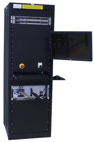
StepWise replaces manual paperwork and instructions with electronic guides to lead operators through the testing of electromechanical components.
With electronic test results, users can trace failures to the serial number for efficient troubleshooting.
Keeping track of part and equipment serial numbers involved in a test is difficult, but necessary to have useful data that can be used to make informed decisions.
Increase Productivity
StepWise allows parts to be tested quickly and accurately.
StepWise can be modified to meet specific needs and significantly increase test process efficiency.
Marked improvements in manufacturing efficiency can be achieved when StepWise is integrated with information on work orders and manufacturing flow from business information systems.
Features
Illustrated instructions for operator assembly and test steps
Customizable graphical interface and program setup
Controlled access for different users
Associates tests with equipment and part serial numbers for traceability
General and customizable test steps
Email alerts for test failures during automated sequences
Separate sequence editor and execution engine
Licensed by site not seat
Proof Points – StepWise Case Studies
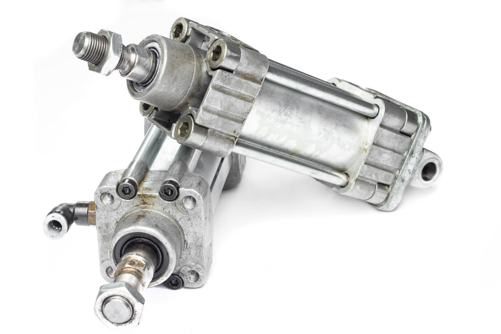
Product Validation using LabVIEW RT & LabVIEW FPGA – Electromechanical Actuator Test Stand
Product Validation using LabVIEW RT & LabVIEW FPGA – An electromechanical test stand for an aerospace actuator
Automated testing reduces operator man hours and increases production throughput.
Client – A manufacturer of actuators in the mil-aero industry.
Challenge
New Product Introduction (in this case a new controller and new actuators) drove the need for a new aerospace electromechanical test stand.
Solution
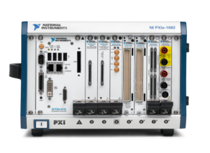
New NI PXI-based electromechanical test equipment provided automated HIL testing, report generation, and SPC data generation. The sequencing of the test procedure, reporting, and verifiable results were managed with the StepWise test executive platform.
Benefits
- Automated testing reduces operator man hours and increases production throughput.
- Meets strict customer requirements regarding testing and data recording in a verifiable manner.
- Automated Test Report Generation.
- Collects data to support SPC (Statistical Process Control).
- Ability to interact with the internal state of the controller FPGA via the LVDS communication link.
System Overview
Viewpoint developed the software and selected NI data acquisition and control hardware for the test stand. There are several layers of software functionality.
| HOST LABVIEW SOFTWARE LAYER |
|---|
| Test sequencer |
| Test steps (e.g. Frequency Response, Step Response, Dynamic Stiffness, Fault Response, Power Consumption) |
| Test Report Generator |
| GUI |
| REAL-TIME (RT) LABVIEW SOFTWARE LAYER |
|---|
| Data acquisition |
| 1553 comms |
| Function generator |
| Error detection |
| ESTOP |
| LABVIEW FPGA SOFTWARE LAYER |
|---|
| Synch data from 3 sources (tester, UUT, external DAQ device) |
| Stream high-speed data to disk |
| Stream high-speed data to analog outputs for HIL test |
| Custom communication protocol used by UUT over LVDS lines |
| HARDWARE RECOMMENDED |
|---|
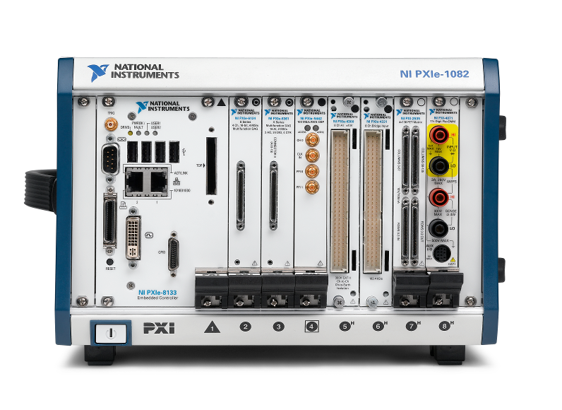
| NI PXIe |
| NI FlexRIO card with LVDS adapter module |
| Multiple NI R Series cards |
| High speed, high voltage, isolated analog input cards |
| INTERFACES / PROTOCOLS |
|---|
| MIL-STD 1553 bus |
| LVDS |
| Ethernet |
| Custom TCP/IP |
*- images are conceptual only, not actual
Increasing Test System Automation for Existing Tester to handle Production Volume Demand Increase
Increasing Test System Automation for Existing Tester to handle Production Volume Demand Increase
Reduced test time across several products by an average of ~25% and reduced time to create paperwork by ~3x
Client
Manufacturer of high-voltage power supplies
Challenge
The client already had an existing manufacturing test system in place. They wanted Viewpoint to enhance the tester due to an increase in production volume demand. Viewpoint reviewed the existing test system and noted 3 areas for improvement:
- Automation available in the measurement instruments – most of the test equipment was automatable, via some combination of serial, GPIB, or Ethernet interfaces. Furthermore, some equipment, such as an oscilloscope, had the ability to store and recall setup configurations. The test operators already used these configurations to decrease setup time for the next test step. Most test equipment did not have automated setup.
- Operator time spent on each test step – the client had been through a Lean assessment and had already done a good job of timing operations. However, we specifically noted that the operator was manually connecting to the test points and manually transcribing to paper the measurement results from instrument displays.
- Automating the connections – many types of product models were being tested at this test system. Connecting the test equipment to all sorts of products would require either 1) many types of test harnesses and connectors or 2) a redesign of the products to make test connections simpler and quicker.
Solution
The enhanced automated test system included automation of instrumentation interfaces, a test executive to run the test sequences, automated test report generation, and automated test data archiving for the electronic UUT.
Benefits
- Reduced total test time across several products by an average of ~25%.
- Time to create paperwork was reduced by ~2/3 due to automated data collection.
System Overview
The enhanced test system included the following updates:
- Test sequence automation
- Automated test report generation
- Automated test data archiving
- Automation of instrumentation interfaces
- Configurable automated test steps associated with each type of measurement instrument. The test operators would create a sequence of steps to setup each instrument and record the resulting measurement. The sequence of steps could be saved and recalled for each product to be tested, so the instruments could be used automatically.
- New programmable meter – integrated the new DMM meter with a programmable interface to replace the one that was not automatable.
- Foot switch integration – Since the connections to the test points were manual, a foot switch allowed the operator to take the measurement and advance to the next step.
The StepWise test executive platform managed the multiple test procedures created for the different products. StepWise also handled creation of HTML reports for every part tested.
| SOFTWARE FUNCTIONS |
|---|
| Test GUI |
| Test Sequencer |
| Report Generator |
| Test Data Archiving |
| Instrument interfaces |
Product Validation & Production Test System – For complex Mission-critical sub-system
Product Validation & Production Test System – For complex Mission-critical sub-system
Upgrade reduces per unit test time by ~40% and improves reliability of software
Challenge
The customer needed to upgrade their existing test system. Their old test system was very manual:
- It did not provide ability for unattended operation
- The thermal control had to be set manually
- They wanted to do less manual review of the data
The client develops mission-critical products, so there’s a desire to reduce manual operations because they have to explain any anomalies, and manual operations are typically more error-prone. They needed repeatable results that they could trust.
Solution
Viewpoint developed a new test system that utilized new hardware and software, augmented by existing low level hardware and firmware. The test system was developed to perform both functional test for production and environmental testing, and was designed to handle up to 4 DUTs at once. The test system utilizes the StepWise test executive software with custom test steps, which allowed the client to create their own highly configurable test sequences. The system was developed in two phases, with the second phase adding support for a FPGA expansion backplane (NI CompactRIO chassis) in order to provide future capability for bringing some of the microcontroller sequence activity into the NI space. In addition, the previous version had a mix of serial, TTL, and USB instrumentation, which was not as robust as Ethernet based instrumentation. Phase II involved upgrading to all Ethernet based instrumentation, and did away with the original test system’s many manual toggle switches that could be used instead of the programmable mode through the SW.
Benefits
- ~40% test time reduction per unit
- ~25% reduction in anomalies that needed to be justified
- ~500 manhours saved in test execution
System Overview
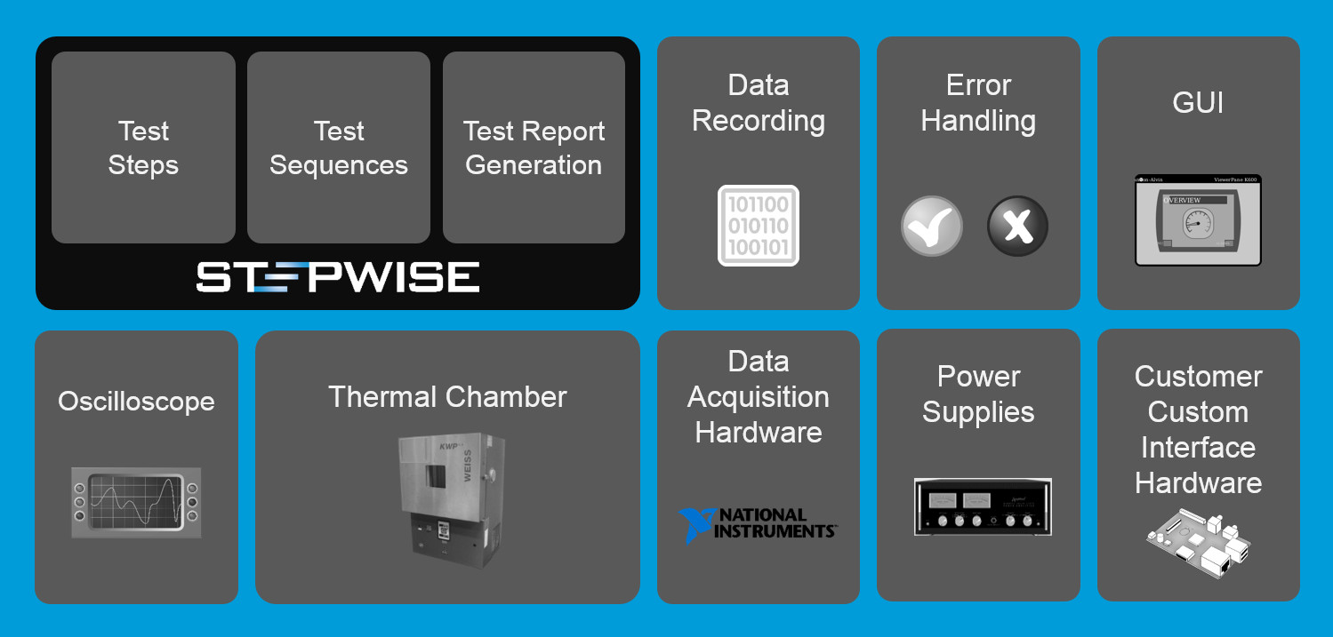
| Software Functions |
|---|
| Test sequencing |
| Test report generation |
| Data recording/logging |
| Error handling |
| Test GUI |
| Oscilloscope interface |
| Thermal chamber interface |
| Power supply interface |
| External custom hardware interface |
Hidden Factory Assessments Lead to Waste and Cost Reductions
Sharing Business and Test Data Enables Efficiency Improvements
Reduce Production Costs by Coordinating Business and Test Data
Client: A major manufacturer of aerospace components
Problem Scope
Many companies operate in a high-mix, low-volume manufacturing environment. In these situations, production of such parts is often complex, with long assembly and test procedures describing the process to make and verify the part. Discussions of automating any part of these processes are often dismissed because an automated test system is thought to be expensive, especially an aerospace test system which requires significant documentation and acceptance testing efforts. Plus, it’s often erroneously thought that each part needs a unique test system.
Challenge
Our client wanted to improve their capability to manage the assembly procedures and get clarity on the status of any parts, whether partially or fully assembled. The existing situation had data manually-entered into a database form or even handwritten data that needed to be transcribed into a database. Often the database was local to the assembly cell. The chance for error was significant and the lag between data collection and updating the database was often days. When questions arose about the status of a particular unit, many hours could be spent in locating and evaluating the associated forms and paperwork.
The steps needed to achieve these goals were clear: automate the collection data on each part while being assembled so that those results would appear in a business-level database which would give a plant-wide view of the status of all the parts in progress.
Thus, this project needed to allow read/write access to sections of the Manufacturing Enterprise System (MES) database so that information about a part being assembled could be obtained automatically and results could be submitted to that MES database automatically.
Solution
We designed the PXI-based system based on the StepWise test executive platform to automate the assembly and testing. This platform enables two significant changes. These changes were made at each assembly cell by having the operator use a test PC and perhaps some measurement equipment as appropriate for the part(s) being assembled at that cell.
First, we replaced all the printed assembly procedures with electronic records so that any operator could review the latest version of the work instructions on a computer screen. This approach helped with version control, especially important since the client had various model revisions that came through the factor for rework, each with slightly different versions of assembly instructions.
Second, we displayed those electronically documented work procedures as steps in a test executive, allowing the results of each step in the assembly procedure to be captured electronically. When an assembly step was purely manual with no measurements, the fact that step was completed would be recorded, along with information such as the name of the operator performing the step, the duration that the step took, and so on. When a step required a measurement to be made, such as a functionality verification or a calibration result, the measurement would be collected. If the equipment making that measurement could be automated, we would collect that data automatically, and not require the operator to type the result into a computer form.
The outcome of this effort has enabled the client to get a snapshot of the status of parts in assembly, i.e., Works in Progress (WIP), quickly and accurately.
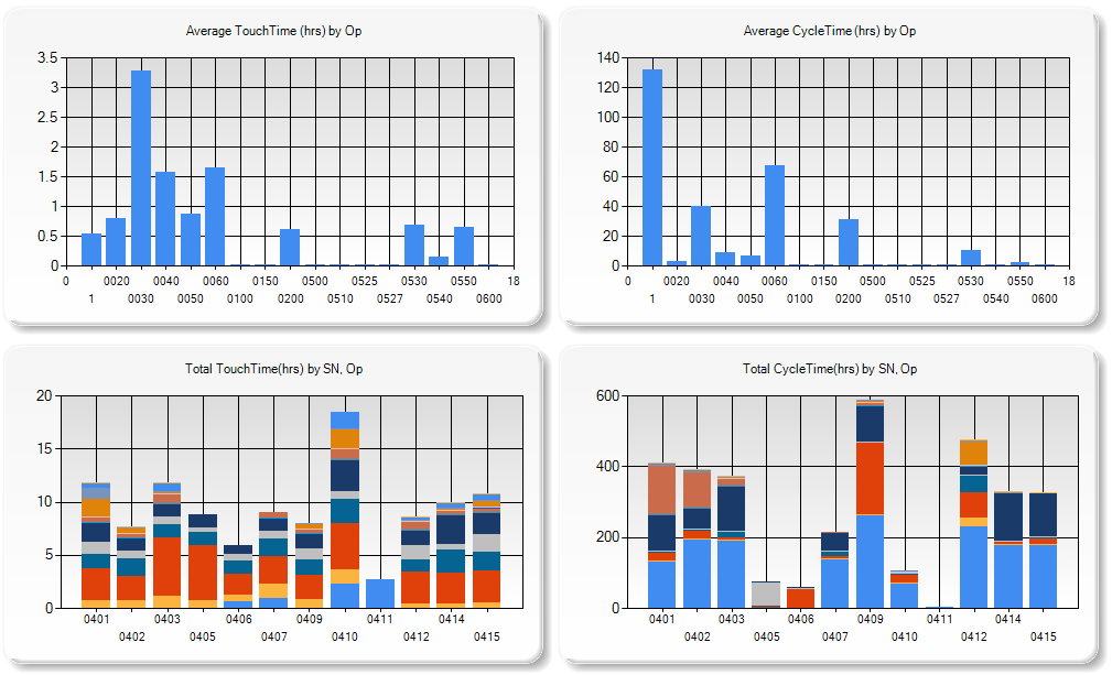
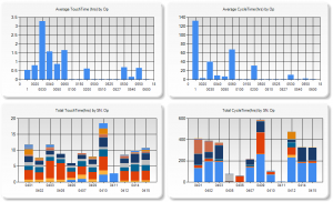
After these changes were made, many additional capabilities are now available with the advent of purpose-built queries into the appropriate MES database tables. The table below shows the overall efficiency gains achieved.
The key is the combination of the electronic test results obtained at the test equipment with information on work orders and manufacturing flow held in the various tables in the business MES database. This improvement happens even with manual or semi-automated test systems, and does not require a completely automated assembly and test system. Thus, the cost of the test system is much less than usually expected and, hence, the benefits are more easily cost-justified.
Production Test of Large Uninterruptible Power Supplies
Production Test of Large Uninterruptible Power Supplies
Manufacturing Test of UPS Units Designed for Data Center Backup Power
Client: A major manufacturer of data-critical three-phase uninterruptable power supplies
Challenge
A major manufacturer of very large three-phase uninterruptible power supplies (UPSs) needed better measurement, analysis, and report generation capabilities. Their clients used these UPSs on mission critical equipment, such as data warehouse server farms, communications equipment, and so one. Existing testing procedures used equipment that did not allow for complete simultaneous coverage of all sections of a UPS unit, from input to output. Our client wanted a better understanding of the signals on each of the three phases at various locations within the UPS, especially when power sources were switched or faults were induced.
Also, in the prior test procedure, factory acceptance reports were manually assembled for our client’s end-customers, delaying the final sign-off. Finally, since the end-customer might want to run a specially configured test or run a series of tests in a different sequence than some other end-customer, our client wanted to be able to rerun certain types of tests or run tests in a customer-specific order. Thus, the test sequencing needed to be flexible and editable, possibly on the fly.
Finally, synchronization between the data collection on all signals was critical to assess functionality, since all 3-phases of the UPS output needed to be in the proper timing relationship.
Solution
At a high-level, the majority of testing a UPS relies on knowing the reaction of the UPS to changes on the input side (such as a grid power outage) and changes on the output side (such as an immediate heavy load). Thus, many of the tests performed on a UPS deal with power quality measurements, such as defined by IEEE 519 or IEC 61000 series standards, which cover both continuous and transient operation. The StepWise test execution platform was utilized to allow the customer to develop arbitrary test sequences using the application specific test steps developed for the program.
Our solution used a cRIO to measure both current and voltage from each leg of the 3-phase power (and neutral) by using appropriate cSeries modules connected to various voltage and current test points within the UPS. The cRIO had enough slots to allow a single cRIO to measure a single UPS.
Assessment of continuous operation mainly reviewed the UPS output power quality. Here, it was important to know the amplitude and phase of each leg of the 3-phase power. Synchronous data acquisition between all voltages and current channels was needed for proper timing alignment of collected data points.
Assessment of transient operation was often a review of power ripple and recovery time. For example, in the event of grid power loss, a UPS would switch over to backup power, with the result being a small transient created on the output a UPS. Again, the voltages and currents needed to be collected synchronously to assure that event timing was aligned.
For increased power capacity, the UPSs could be connected in parallel. When ganged together, the continuous and transient behavior of each UPS needed to be compared to the others, in order to capture the behavior of the entire combined system. Consequently, each cRIO (one per UPS) had to share a clock to enable synchronous data collection across all cRIOs. A timing and synchronization module was placed into each cRIO chassis with one cRIO acting as the master clock source and the others being slaved to that clock.
The overall test system architecture has a master PC communicating with each cRIO. Each cRIO was placed in certain activity states by the master PC, such as “arm for measurement”, “transfer collected data”, and “respond with system health”. This arrangement enables the number of cRIO to shrink or grow depending on the number of UPSs being testing in parallel.
Results
The test system connected the timing module in each cRIO in a daisy-chained configuration, leading to data sampling synchronization error of less than 100 ns between all cRIOs, which translates to about +/-0.001 degree phase error for 60 Hz power signals. This timing synchronization was more than sufficient to analyze the collected waveform data for power quality and transient structure.
LabVIEW was used to create various configurable test steps that could be executed in random order as well as in an automated sequential manner. Our client was thus able to test a UPS in a predefined manner as well as react rapidly to queries from their customer when they were viewing a factory run-off test. For example, the customer might ask to re-run the same test several times in a row to validate consistent responses.
Each type of test included automated analysis routines that numerically calculated the relevant parameters against which the UPS was being checked. Not only was this automated calculation faster, but it reduced mistakes and improved reproducibility as compared to the previous post-testing partially manual calculations.
Data from all tests, even repeated ones, on a given UPS were archived for quality control purposes and made a part of the device history for that UPS.
Finally, the report generation capability built into this test system was far superior to the previous methodology by allowing our client to hand their customer a professional report package practically immediately the testing was complete. Customer satisfaction was improved substantially with this state-of-the-art test system.
Improving Efficiency in Industrial Manufacturing Test
Improving Efficiency in Industrial Manufacturing
Simplifying Report Generation for High-Mix, Low-Volume Industrial Servo Valve Tests
Client: A major industrial servo valve manufacturer
Challenge
A manufacturer of components for both commercial and military aircraft built a large number of different models of servo valves. Some models were made only a few times each year, while other models were made with an order of magnitude higher volume. Each unit underwent rigorous testing during and after assembly.
Our client needed to submit the results of that testing to their customers but since the production and testing of each unit happened in many locations, possibly even around the world, many hours were spent locating the appropriate datasets and assembling the report.
Furthermore, our client wanted to improve their responsiveness to requests from their customers by having rapid retrieval of the test report for any part after it had been delivered into the field.
Solution
Since the test datasets were varied due to the large numbers of different valve models and associated test procedures, a database was created using a platform based on the Resource Description Framework (RDF). An RDF database can accept arbitrary types of data, manage that data through metadata tags, and adjust gracefully to changes in content and shape of the connections between objects in the database.
This adaptability was key to our client being able to leap past some of the issues in standard SQL-based relational databases.
The results from each test run on each part at each (PXI-based) test system were tagged with metadata and pushed into the RDF database. The StepWise test executive platform interfaced to the RDF database by outputting XML content which was scanned by a routine created for the RDF database and converted into the RDF data and links. The part ID was a critical tag since this allowed searching the RDF database for all results associated with that specific part. This database resided on a server at the client’s headquarters and accepted data from worldwide locations.
Once the data for each part was housed in the database, a report could be generated. To accommodate the variety of data in that report, web technology was used to render the report pages based on the types of data entered into the database, as described by the metadata tags. For example, data identified as waveforms could be plotted or listed in tabular format. Having reports rendered based on the data types made it possible to handle adjustments to the types of data measured by the test system.
Results
With the ability to render reports quickly, our client could produce detailed reports for their customers indicating the performance of any specific requested servo valve.
Our client was able to trim the time to create reports to less than 1 day from the previous effort of 3-5 days and with less error.
- Data are now organized uniformly, simplifying the location of desired information, as compared with files stored on various test PCs and file servers.
- The client has the ability to generate automatic emails to their customers with the required reports already attached and ready to go.
- In potential warranty and customer service situations, having the ability to send the customer a report within hours represented great customer service.
All these features are available consistently across worldwide manufacturing facilities, reducing training and maintenance of procedures. And, of course, the reports handle using metric or English units as appropriate for the end customer.
| Find out if StepWise is right for your application |
|---|
Videos
Want more proof that StepWise works?
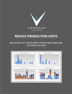
Check out this report where we show you how we helped one of our clients reduce production costs by up to 30% by integrating StepWise with a test database and their business systems.
See here for StepWise screenshots.
See here for StepWise version info.


