LVDT Test Instrument
Stringent measurement requirements apply when fully characterizing an LVDT or RVDT device for use in Aerospace or Military programs. Whether for product design validation or manufacturing test, tight accuracies are needed for measurements of raw signal amplitudes, ratios from secondaries, and associated linear or angular positions.
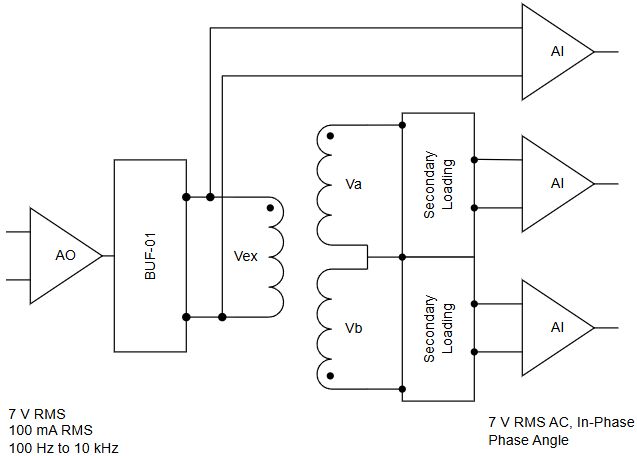
Our LVDT Test Instrument uses NI’s Compact RIO (cRIO) hardware for its FPGA-based signal output and acquisition to enable accuracies even better than some high-end phase angle voltmeters. The analog outputs couples with Viewpoint’s BUF-01 module, for high current compliance output, to drive the primaries. Up to four simultaneous LVDTs / RVDTs can be tested concurrently.
Due to the myriad hardware and software configurations available, please call for pricing on the exact configuration that will meet your needs.
Why Viewpoint’s Test Instrument?
One reason we developed this product is our concern that some existing phase angle voltmeters are going obsolete. Our product offers a future-proofing path forward, especially since it is based on COTS components.
The COTS components and our software enable testing of LVDT/RVDT devices by offering signals to drive the primary with a current compliance of up to 200 mA peak (140 mA RMS) with the addition of FPGA-based clocking for precision synchronous timing of all analog I/O.
The high current compliance comes from our BUF-01 module which can convert NI’s voltage analog output to high-current levels.
The tight time-synchronization reduces measurement error in phase angle determinations and amplitude-based, e.g., ratio, calculations.
Some additional details about our device are:
- The BUF-01 module takes the NI module’s bipolar analog output of ±10 V (7 V RMS) and supplies up to 200 mA peak (120 mA RMS) current compliance.
- Up to 4 LVDT/RVDT units can be tested per chassis.
- Source code is available for all but a few proprietary VIs.
- DIN rail mountable for field wiring connections.
- Channel counts, connectivity, and capabilities can be customized to specific needs.
Application Overview
This product can be configured to test one or up to 4 LDVT/RVDT sensors per cRIO chassis.
Each sensor is tested by driving its primary input by an analog signal output by a cRIO AO module and the sensor two secondary outputs are digitized by a cRIO AI module.
All I/O uses a cRIO FPGA clock for high-accuracy, simultaneous measurements, providing phase synchronicity for critical measurements. And this synchronicity applies across all modules in the chassis.
Key Specifications
