LVDT Simulator
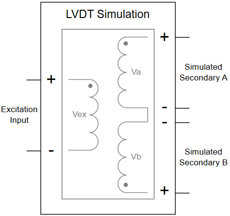
The LVDT Simulator is a device that creates signals as would be output from the secondaries of an actual LVDT or RVDT. In addition to the baseline ability to adjust signal amplitudes, phases and other conditions, the LVDT Simulator is ideal for creating conditions needed for full simulation of actual hardware such as fault injections, nonlinearities, secondary imbalances, and so on.
Built on NI’s Compact RIO (cRIO) platform, the LVDT Simulator uses LabVIEW FPGA software with a REST API for external control. Up to 4 simultaneous simulators, 2 output channels per simulator, are allowed for each cRIO chassis.
Due to the myriad hardware and software configurations available, please call for pricing on the exact configuration that will meet your needs.
Application Overview
This product can be configured to simulate one or up to 4 LVDTs / RVDTs.
Each simulated device takes an analog input as excitation and outputs signals to simulate the A and B secondaries.
The two secondary outputs are created by digitizing the analog signal input to the simulator cRIO hardware and manipulating this input. For example, the secondaries are scaled and delayed copies of the, usually sinusoidal, input signal.
The scaling and delays are adjustable via a REST API which provides precise control of the output signals and simulation of faults.
More complicated simulations can be created by us through changes to the simulation code running on the cRIO controller. Please contact us for more details.
Why Viewpoint’s Simulator?
For the typical use case of simulating redundant and/or critical LVDT / RVDT subsystems in aerospace and defense, we offer the following advantages:
- Cost-effective platform based on NI cRIO and LabVIEW FPGA with up to 4 channel configurations per cRIO chassis.
- Source code is available for all but a few proprietary VIs.
- DIN rail mountable for field wiring connections.
- Channel counts, connectivity, and capabilities can be customized to specific needs.
Key Specifications
